7.5 THRUST-VECTOR CONTROL
To steer a vehicle over its trajectory, thrustvector control is applied. The following methods have found application: (1) Gimbaled thrust chamber or engine assembly (widely used) (2) Jet vanes (obsolescent) (3) Jetevator (4) Gimbaled thrust chamber nozzle (rare with liquid propellants) (5) Secondary injection (into the thrust chamber) (6) Auxiliary jets
The first method is used most frequently, due to its inherent reliability and performance. The first four systems require actuators which may be operated by hydraulic, pneumatic, or electric means. The remaining systems are controlled by flow regulation.
Thrust Vector Control Systems Using Actuators
Figure 7-7 presents a simplified schematic for a thrust vector control system, employing hydraulic or pneumatic actuators. It may serve to explain the fundamentals of closed-loop thrust
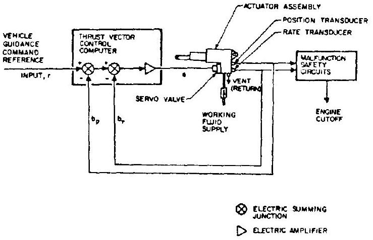 Figure 7-7.-Typical schematic of a thrust vector control system using hydraulic or pneumatic actuators.
vector control, even though the systems used in practice may differ significantly in detail. The actuators are controlled by commands, originating in the vehicle guidance system, which are a function of the vehicle's deviations from a prescribed path and of its response to corrective steering action. These signals are fed through an electronic thrust vector control logic to servo valves. In the system shown in figure 7-7, each servovalve modulates the fluid flow to its respective actuator assembly in response to an electrical error signal which is proportional to the difference between desired actuator position and its actual position. Feedback of the actual position is obtained through a transducer attached to the actuator. Additionally, the actuating speed is sensed by a rate transducer and applied to the control computer to stabilize the closedloop control through adequate damping. Instead of a rate transducer, electronic differentiation of the position transducer output may be applied
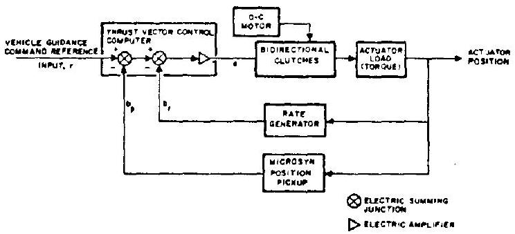 Figure 7-8.-Typical schematic for a thrust vector control system using electromechanical actuators.
toward the same end. Malfunction safety circuits are included to effect engine cutoff in the event of erratic operation.
A typical schematic for a thrust vector control system using electromechanical actuators is shown in figure 7-8. Here, the actuator is powered by a continuously operating, constantspeed, 28 volt dc motor, fitted with dry-powder metal bidirectional clutches. The control computer consists of summing junctions and an amplifier as in the case of hydraulic actuators. The dc motor drives the actuator through the bidirectional clutches which are controlled by the error signal generated through comparing guidance command reference input with systems position feedback. To provide adequate systems damping, the actuating speed is sensed by a rate generator or through differentiation of the position signal.
Apart from electrical feedback and compensation systems, mechanical feedback systems coupled with hydromechanical compensation "networks" are coming into increased usage. They are inherently simpler and thus offer higher reliability. Two basic types of hydromechanical compensating devices may be distinguished: piston-bypass devices and load-pressure-sensing devices.
Piston-bypass devices utilize leakages past the actuator piston to introduce system damping and may make use of dynamic relationships to control time constants (a hole drilled through the piston is an example).
Load-pressure-sensing devices, commonly called "pressure feedback" (PQ) valves or "derivative pressure feedback" (DPQ) valves, are widely used.
Figure 7-9 shows a typical servovalve and actuator schematic with derivative pressure feedback (DPQ) and mechanical feedback. The only electrical signal required is the input to the "torque motor" (an electromagnetic actuator) resulting in deflection of the flapper of a differential valve, which drains to the sump. If the flapper is deflected, as indicated in figure 7-9 by the arrow, nozzle flow on side decreases, with an attendant pressure rise. The reverse is true for side . The resulting pressure differential forces the power-stage spool to the left, blocking the return line on side , and opening it on side . As a result, pressure increases,
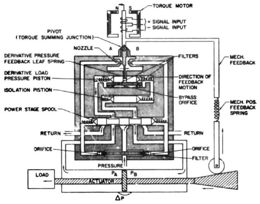 Figure 7-9.-DPQ valve with actuator.
and decreases, forcing the actuator piston to the left to apply the desired load force. Attached to the actuator piston rod is a tapered extension which acts upon the mechanical feedback linkage, including a roller and a spring. The mechanical feedback attaches to the torque motor. The pivot point of the valve flapper becomes the error torque summing junction. Note that the nozzle jets also have a feedback effect. The time derivative of the actuator motion, i.e., the hydromechanical compensation, is obtained through action of a derivative load pressure piston. This piston is affected by the same pressure differential that acts upon the actuator piston; i.e., by the load pressure. However, by inserting an isolation piston and permitting flow through an orifice bypassing the derivative pressure piston, the pressures affecting the latter can equalize. The degree of this effect is a function of the actuator pressure differential and its rate of change and of the bypass orifice size (shock absorber principle). As seen in figure 7-9, the derivative load pressure piston acts upon the valve flapper when displaced. Thus it provides the required time derivative of the actuator motion for compensation.
As has been seen it is possible to provide compensation in thrust-yector-control systems by either electrical or hydromechanical means, the latter now being often preferred for actuators. Conceivably, other control systems could be converted from electrical to hydromechanical networks. The analogies between the differential equations of the two network types often permit the use of existing electric 1 networks and transfer functions by substituting the equivalent hydromechanical time constants.
Table 7-2 may be found valuable by those who wish to familiarize themselves with some fundamentals in this field. Detail on the design of servovalves will be found in section 7.11.
Demonstration Example
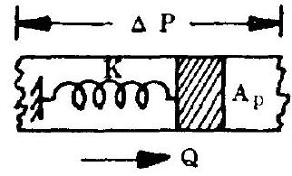
Two basic types of electrical compensation networks exist: current output for voltage input, and voltage output for voltage input networks. Figure 7-10 shows a simple form of a current output for voltage input network. Find the analogous hydromechanical network.
Solution
The transfer function for the electrical network is
where i = electrical current (amps) voltage (volts) resistance (ohms) C = capacitance (farads) LaPiace transform operator ( for sinusoidal forcing functions) From table 7-2, we obtain the equivalent hydromechanical parameters for , and . The new transfer function then is
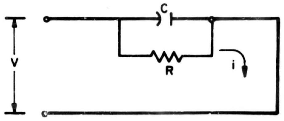 Figure 7-10.-Current output for voltage input nétwork.
TABLE 7-2.-Electrical-Hydromechanical Component Analogies
| Electrical quantity or component | Describing equation | Hydromechanical component or quantity | Describing equation | Analogy | Remarks |
|---|---|---|---|---|---|
| . voltage drop, volts. . . . . . . . | . pressure drop, psi | ||||
| i, current coulombs/sec....... | coulomb charge | Q, flow, in | volume | ||
 | Massless piston assumed | ||||
| piston area, spring constant, | |||||
 | | Parabolic flow curve linearized about operation point | |||
| Resistor, ohms | Orifice, | ||||
 |  | Piston mass not negligible | |||
| Inductor, henries | piston area, in piston mass |
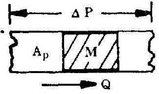
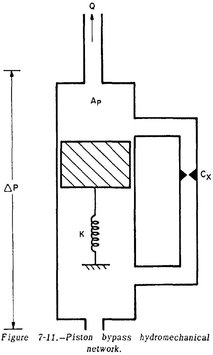
[^7]The correct hydromechanical network, which is of the piston-bypass type, is shown in figure 7-11.
Engine-to-Vehicle Interfaces With Actuator Systems
Engine Installation and Alinement
For minimum demands on the vehicle guidance and engine actuation systems, it is required that the engine thrust vector be properly prealined with respect to the vehicle attachment point in all three planes. Typical specified tolerances are: inch laterally, vertically.
The significance of good thrust alinement can be seen from the fact that in an engine cluster, at the randomly distributed maximum of these tolerances, a trim deflection of close to would be required from all engines to offset the misalinement.
For larger (looser) alinement tolerances, the trim deflection would be further increased. Even if the trim deflections seem to reduce effective thrust and guidance capability only slightly, the need to apply them for the full duration of powered flight results in appreciable payload reductions.
It is customary to aline the engine thrust vector to the upper face of the gimbal bearing prior to shipment. Both optical and dynamic
 methods (load cells) are used. The optical or cold alinement establishes the geometrical location of the thrust vector in the shop, through finding the centers of nozzle throat and nozzle exit, and alining their connecting line perpendicular to the gimbal plane. A simple plumb attached to the injector center may be used in support of this operation. Subsequently, during engine firing, this measurement may be confirmed dynamically using side load cells in lieu of gimbal actuators. As a rule, after a few engines have been alined in this manner, experience will permit meeting specification by optical means alone. The vertical alinement can be simply documented as the eye-to-eye distance of the actuator attach points, or as the line through two index points (fig. 7-12). Lateral dimensions can be marked in a suitable manner at or on the gimbal bearing face. If the mating vehicle face had been properly alined to the vehicle axes,
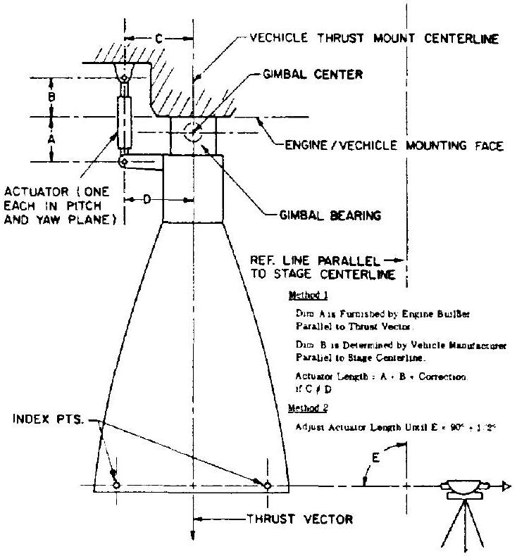 Figure 7-12.-Engine alignment.
installation of the engine then simply consists of attaching it, observing the engine logbook specifications. Figure shows installation methods of a prealined engine into the vehicle. For the first vehicles of a new type produced, it is advisable to specify verification of engine alinement following transportation to the launching site.
Actuators, Loads
Actuators are usually of the hydraulic-piston type. Hydraulic-rotary, electromechanical, and pneumatic turbine-driven types have also been investigated.
Engine gimbal actuators are attached to the engine at one end, and to the vehicle at the other (fig. 7-13). They may be procured by the vehicle builder or by the engine builder, and must be properly dimensioned. The attachment points at either end must be capable of absorbing the forces encountered with an adequate reserve. As a rule, two actuators are required for each engine. Together, they permit deflection of the engine in all directions. It is important to note that if the maximum deflection effected by an individual actuator, for instance, is , the combined maximum angle ("corner deflection") of a pair is approximately . Inlet ducts, flex lines, gimbal bearing, and possibly
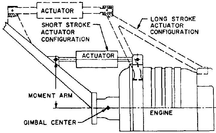 Figure 7-13.-Engine actuator installations.
other components affected, must be able to "take" this deflection. If their capability is limited, proper gimbal restriction (stops or snubbers) must be provided (circular gimbal pattern instead of square).
Selection and design of the actuators is based on the gimbal forces required. In a typical case, the actuator force may be 25 percent of the engine thrust level. The force is determined by considering the following:
Inlet duct reactions Flexible service line reactions Gimbal bearing friction Heat shield reaction (if any) Correction for misalinements Aerodynamic loading (if any) Vehicle acceleration effects Inertia of gimbaled mass Miscellaneous minor effects
It is stressed that the engine design should reduce these forces to a minimum for smallest size and lightest weight of hydraulic pump, actuators, and associated equipment. Recognition of this need and careful design can do much toward this goal. The system must be capable of stable, well-damped response when cold gimbaled, such as during prelaunch checkout, even though the loads encountered here may be quite different from those occurring during engine firing. This dual-load situation may pose serious problems.
During startup of the engine, brief peak side loads in excess of those occurring during normal gimbaling can be generated by the thrust chamber itself. This is especially true for high expansion area nozzles being developed at sea level (for engines designed for altitude operation), where filling of the nozzle takes a longer time during buildup than with shorter ones. Unless these loads can be eliminated or at least reduced, they must be considered for the design of actuators and attach points at both ends (notification of vehicle builder).
Crosstalk and Spring Rate
Since engine and vehicle designer are not entirely free regarding actuator installation, a situation may exist wherein motion of the actuator in one plane affects the other actuator in its plane. This is referred to as "crosstalk." If it is excessive, control instabilities may develop. Therefore, close coordination between engine designer and vehicle builder to minimize crosstalk is essential.
The actuator must be able to translate its motion without delay into engine deflection. If the control loop formed by actuator, engine structure, and vehicle thrust structure is "soft," i.e., if it has a low spring rate ( ), the engine does not react promptly to an actuator motion as called for by the guidance system. A delay with subsequent overshoot and continued oscillation may result. The natural frequency of this oscillation is a function of actuator stroke per degree engine deflection, feedback gains, and compensation network parameters.
Figure 7-13 shows two typical engine actuator installations. The short-stroke configuration has the advantage of high spring rate and high stiffness, and of compactness. However, the effective gimbaled mass is high, requiring larger actuators and a more powerful hydraulic system. Resolution is low (gain, expressed in degrees deflection per inch actuator stroke, is high). The long-stroke design results in low effective gimbaled mass and reduces actuator size and hydraulic system dimensions. However, the spring rate is low and so is the stiffness. Moreover, the arrangement is bulky and requires extra structural members. Only a detailed design analysis conducted jointly by engine and vehicle designer will determine which configuration is best for the flight system.
Hydraulic System
Until other means are available, a hydraulic system is probably required to power the engine actuators. Its basic elements are:
Hydraulic pump Reservoir (low pressure, or "sump") Accumulator (high pressure) Servovalve Actuators Feedback (electric or mechanical) Lines, check valves, filters, connectors, instrumentation If continuous hyr raulic power is required prior to engine st- ,, such as for recirculation of the hydraulic fluid or for gimbal tests, an electrically driven auxiliary pump is also provided. In most instances, the auxiliary pump will be operated until venicle liftoff only, and can, therefore, be ground powered. For upper stages, the accumulator will then provide, for a limited time, the hydraulic power required during staging and turbopump buildup following its unlocking.
Since some of these components will be part of the engine system, while others are stage mounted, an important vehicle/engine interface exists. Through an auxiliary drive shaft, the main hydraulic pump may be driven from the engine turbopump. It is connected to the other hydraulic equipment and to the actuator through high-pressure lines, several of which must be flexible. These other elements may be mounted on the vehicle at the expense of longer lines which also must cross the gimbal plane and must therefore be flexible. Or, they may be engine mounted. This, however, increases the engine gimbaled mass and may pose space and envelope problems. To compensate for misalinements and thermal expansion and contraction, a cercain amount of flexibility must be provided for the lines even in this case. It is possible to connect an electric generator to the main turbopump, and drive electrically a stage-mounted hydraulic pump. Only electrical wires will then cross the gimbal plane, with the exception of the hydraulic lines to the actuators which always must be flexible. Another possible simplification is to combine servo valve and actuator into one single unit. Figure 7-14 shows a typical hydraulic engine actuation system. Figures 7-15 and 7-16 may serve to identify the major components of this system.
From the above it becomes apparent that numerous hydraulic connections will have to be made when installing the engine into the vehicle. All of them must fit, and permit adequate flexure,
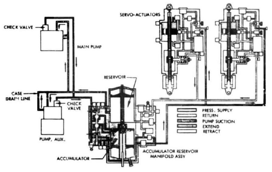 Figure 7-14.-Engine actuation system schematic (hydraulic).
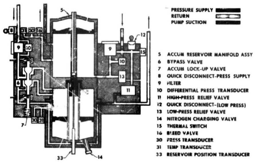 Figure 7-15.-Accumuiator-reservoir schematic.
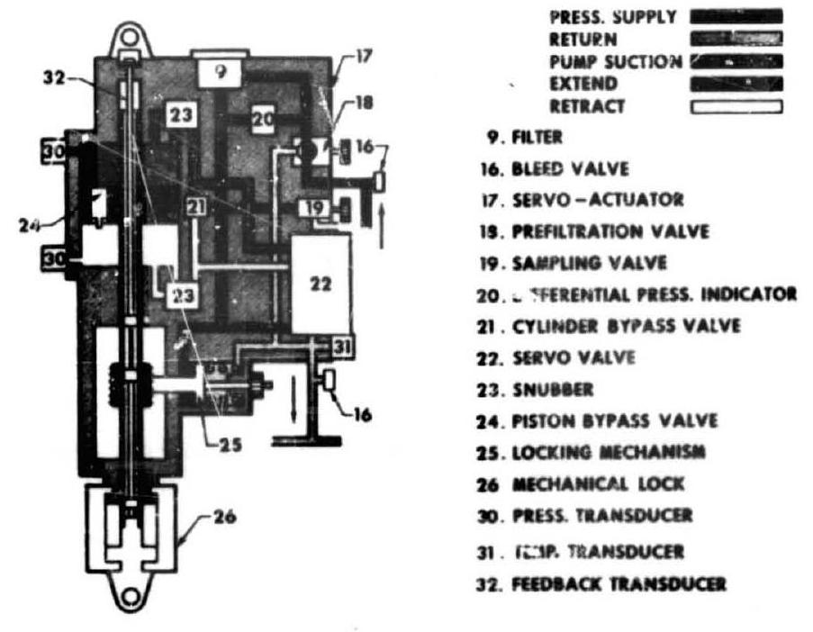 Figure 7-16.-Servoactuator schematic.
must be long enough and of the proper pressure rating, and, above all, must have a mating part on the vehicle.
Furthermore, the designer must know and consider the environment in which the hydraulic system will perform. The narrow-tolerance components and the hydraulic fluid are very temperature and contamination sensitive. Thus, the designer will have to specify extreme cleanliness requirements and adequate temperature conditioning for maximum reliability of this vital system. On cryogenic engine systems, heating of the more sensitive components of the hydraulic system is often required. Grou. supplied and thermostat-controlled electric heaters, which disconnect at liftoff, are a favored temperatureconditioning method. Continuous recirculation of the hydraulic fluid by means of the aforementioned ground electrically driven auxiliary pump is another.
Secondary Injection
Thrust vector control through secondary injection of matter into the thrust chamber nozzle (SITVC) has been successfully applied to solid motors. It has found only limited, predominantly experimental application in liquid propulsion systems, where it appears especially promising for upper stage engines, in which the lateral forces required are smaller than with boosters. The principal methods of secondary injection are- (1) Gas injection, using- (a) Inert stored gas (b) Thrust chamber tapoff (fig. 7-17A) (c) Gas generator (fig. 7-17B) (2) Liquid injection (fig. 7-17C), using- (a) Inert fluid (b) Propellants
Other methods, such as injection of preheated hydrogen, have been investigated but proven uneconomical.
In a gimbaled thrust chamber, the side force is located approximately at the injector end. With an SITVC system, the applied side force is located downstream of the nozzle throat and approximately at the point of injection, resulting in an increased moment arm which decreases the required side force.
Performance Evaluations
The performance of any type of secondary injection system is based upon two performance
 Figure 7-17.-Secondary injection systems.
factors: amplification ( ) and axial thrust augmentation ( ). These factors are defined as follows:
where secondary flow rate, lb/sec primary flow rate, side force, pounds undisturbed axial primary thrust, pounds axial thrust increase, pounds undisturbed axial specific impulse of the primary chamber (seconds) side specific impulse (seconds) secondary axial specific impulse (seconds) Essentially, the factor determines the quantity of fluid required to obtain the side force, and the factor determines the penalty on the overall system to obtain the required side force. If both of these factors are known, the total effect of a given secondary injection system on a propulsion system may be determined.
The factor determines the quantity of secondary injectant fluid required (for a known duty cycle); the maximum flow rate; the additional tankage, pressurization fluid, and secondary injection hardware weight; and the effect of the added inert weight on vehicle trajectory. The factor evaluates the penalty on the propulsion system. If is equal to 1 , the specific impulse of the secondary fluid is equal to that of the primary fluid and, therefore, the propulsion system suffers no specific impulse penalty due to the SITVC system.
Both the amplification factor and the thrust augmentation factor are influenced by the secondary injection orientation. For each application, a tradeoff must be made between the two factors to determine the optimum injection orientation for maximum propulsion efficiency. Let the force of an external jet of comparable geometry at right angles to the primary nozzle be unity. Then amplification factors greater than 2 are obtained if secondary injection is made with the nozzles pointing upstream, rather than in a normal or downstream direction. Side forces for a given are further increased if injection is made through a series of holes arranged on a horizontal arc, rather than through a single orifice. Note that the manifolds required in this case may adversely affect response, however. Test experience suggests that overall pressure ratio and injector size appear to have little effect, while gas temperature does, optimum values being a function of propellant combination.
For an oxygen/hydrogen tapoff system, the range between and appears most favorable; however, as with turbines drives, material strength and cooling problems will dictate values substantially lower, say . In a typical tapoff SITVC system, the gas flow rate may be 1.5 to 2.5 percent of the primary llow rate, the upper value indicating the situation of maximum force required between two injection stations (two jets operating). The tapoff system offers simplicity and good performance. However, with low-duty cycles, a continuous bleed may be necessary to maintain temperatures at the valves.
The performance of a gas generator SITVC system is comparable to that of a tapoff system, probably slightly better. This is offset by higher complexity (valves, injectors, ignition, cooling).
Liquid injection systems (inert fluid or propellants) offer the simplest arrangement. This is offset by their low performance, -factors being in the order of unity, at flow rates from 5 to 6 percent of the primary flow. However, in systems with low-duty cycles, they may still be very attractive.
As a rule, four elements are required for a given system, equally spaced on the main chamber circumference, of which no more than two adjacent ones would be operating at a given time. The control of the required valves is accomplished through a logic and a servosystem analogous to that of a hydraulic gimbal actuator system.